Monday, March 28, 2016

Maximum Power Transfer

According to Thevenin's theorem, when a load resistance is equal with the Thevenin's resistance, the

maximum of power will delivered to the load.

Figure 1: Graph of  the Power vs Load Resistance


Figure 2: Calculation of the  Load Resistance in Maximum Power delivered to it
According to the below circuit, the load resistor is changed, and its drop voltage are measured by

a DMM. Then, load power is calculated, and the graph of load power vs load resistor is sketched by

Excel.

Figure 3: The Schematic of Circuit

According to the below data table, the maximum power equal 1.33 milliwats is delivered to the load

resistance equal to 4.98 K.

According to the figure 3, internal resistor 4.63 K is measured by a DMM.

So Percent Error = [(4.63 - 4.98) / 4.63]*100% = 7.6%


Figure 4: Data Table of the Load Resistance


Figure 5: Graph of the Load Power vs Load Resistance


Monday, March 21, 2016

Class Activity (Week 4)

In this week, Thevenin's Theorem, and Norton's Theorem are investigated.

Thevenin's resistor and Norton's resistor is equal. Thevenin’s Theorem states, in any linear electric

circuit consisting of a combination of voltage or current sources and resistors can be replaced by a

single voltage source with the Thevenin voltage, Vth and a single internal resistance equal to the

Thevenin resistance, Rth.

Figure 1: Thevenin's Theorem

In order to find Rth, current sources must be open, and voltage sources must be short-circuit.

Figure 2: Norton's Theorem
In order to find I(Norton), Thevenin's voltage can be used, or the current passes through between a and b can be found.

The Superposition Method

When a linear system sources exist in a electrical circuit, superposition method can be used. In this

method all sources eliminate except voltage source one, and all of branch currents or branch voltages

are calculated. Then, all sources eliminate except voltage source two, and all of branch currents or

branch voltages are calculated. Finally, branch currents in each stage can be added to determine true

current value.

Figure 3: Superposition Method

Figure 4: Real voltage of circuit 


Thevenin's Theorem

In this lab, Thevenin's Theorem not only is investigated experimentally but it is determined analytically as well. A variable load resistor is connected between points a and b.


Figure 1: Thevenin's Theorem Circuit

All of resistors are measured by a digital Ohmmeter, and those are written by red color (Fig 1).

Figure 2: Calculation of Thevenin's Voltage

According to measured resistors in the above circuit, Thevenin's Voltage is calculated.

(2.17 + 4.58)*I1 = 2-5
(6.65 + 6.69)*I2 = -5         , I1 = - 0.444 A , I2 = - 0.375 A

 Vc - 4.58*I1 + 6.69*I2 = Vd , Vc - Vd =  Vth = 4.58*(-0.444) - 6.69*(-0.375) = 0.475 v

Theoretical Thevenin's voltage is 0.475 v , and experimental Thevenin's voltage is 0.47 v (Fig 1).

Percent Thevenin's Voltage = [(0.475-0.47)/0.475]*100 = 1.1%

Percent Thevenin's Resistor = [(7.4 - 7.31)/7.4]*100 = 1.22%  

Figure 3: Thevenin's Voltage is measured 0.47 volts

When the load resistor changes, its drop voltage will measured by a digital voltmeter, and it records in order to determine drop power of the load resistor.

 
Load Resistor (Ω)
Drop Load Voltage (v)
Drop Load Power (W)
2.17E+03
0.108
5.38E-06
3.53E+03
0.153
6.63E-06
4.62E+03
0.183
7.25E-06
5.61E+03
0.204
7.42E-06
6.80E+03
0.227
7.58E-06
7.40E+03
0.238
7.65E-06
8.02E+03
0.247
7.61E-06
9.80E+03
0.27
7.44E-06
1.78E+04
0.334
6.27E-06


When P(load) is maximum?

At now, circuit has a voltage source equal Thevenin's voltage, and a resistor equal Thevenin's resistor. In this situation, when R(load) is equal with Rth, P(load) will be maximum.

P(load) = [(Vload)^2] / RL , V(load) = [RL / (RL+Rth)]*Vth → P(load) = (RL)*[Vth / (RL+Rth)]^2

Derivative of P(load) relative to RL equal zero is [(RL+Rth)^2] - (RL)*[2*(RL+Rth)] = 0

(RL+Rth) - 2*RL = 0 , RL = Rth


According to the above table, P(load) is maximum when RL is equal 7.4 k.

This is the formula P(load) = (RL)*[0.47/(7400 + RL)]^2 that graph figure 4 follows.

Figure 4: Load Power vs Load Resistor


According to above table, RL is chosen exactly equal Rth, and under this situation load power is maximum.

Sunday, March 20, 2016

Time-Varying Signals

In this lab a voltage divider is used by two resistors. Output voltage is a linear function of input voltage as shown in Fig 1.

Figure 1: Time-Varying Signals
Vout = [R2 / (R1 + R2)]*Vin , When R1 = R2 then Vout = (1/2)*Vin
This circuit never change the shape of input wave. the output voltage is a coefficient of the input voltage. Input signals sinusoidal, triangle, and square are connected to the circuit, and output voltages are again sinusoidal, triangle, and square. Only the output voltages amplitude are half of input voltage amplitudes.
Frequency of input and output voltages are the same, and it calculates with oscilloscope. According to time division on oscilloscope and f = 1/T , frequency is measured.

Figure 2: Triangle and Square waves

Figure 3: A Sinusoidal wave

Figure 4: A Triangle Wave

Figure 5: A Square Wave

Vin = 2 volts for the sinusoidal, triangle, and square waves, and Vout = 1 volt. f = 1000 Hz


Monday, March 14, 2016

Class Activity (week 3)

This week node voltage and mesh current analysis teach. When a dependent or independent voltage

source is between two essential nodes, this is a super node. Voltage source can temporary delete in

this situation. According to Fig 1, independent voltage source between V2 and Vx is inside a super

node. Equations in the figure 1 show that Vx = 30 volts.

Figure 1: Super Node in a DC Circuit


In the below circuit a mesh current method use. There is two essential nodes and three branches, and

two loops choose. Two KVL are written for each loop, and a system equation with three independent

variable are solved by Cramer's Rule. Also current in the middle branch is i1 plus i2.


Figure 2: Mesh Current Method 

When a dependent or independent current source is between two essential nodes, this is a super

mesh. Current source can temporary delete in this situation, but its effects will consider in KVL.

The independent current source in the second loop is in the super mesh. This current source delete,

but it determine that i2 - i3 = 3A.


Figure 3: A super Mesh in a DC Circuit
Everycircuit.com is a cite that help people make their circuit easily.


Figure 4: Everycircuit.com
A NPN bipolar transistor as a current control a current source is connected, and its gain calculated.

α = β / (β + 1) , α = 50 / ( 50 + 1 ) = 0.98039

α = IC / IE , α = 8.25 mA / (0.165 + 8.25) , α = 0.98039

Figure 5: A Bipolar Transistor


A BJT Curve Tracer

Bipolar Junction Transistor (BJT) is a Semiconductor device constructed with three

doped Semiconductor Regions (Base, Collector, Emitter) separated by two p-n Junctions, 

The p-n Junction between the Base and the Emitter has a Barrier Voltage (V0) of 

about 0.6 V, which is an important parameter of a BJT.

BJT NPN symbol (case).svg
Figure 1: A NPN BJT Schematic Symbol

BJT PNP symbol (case).svg
Figure 2: A PNP BJT Schematic Symbol

Typically, the emitter region is heavily doped compared to the other two layers, whereas the majority charge carrier concentrations in base and collector layers are about the same. A cross section view of a BJT indicates that the collector–base junction has a much larger area than the emitter–base junction.

Figure 3: A Cross Section of a Planar NPN BJT

.Charge flows in a BJT is due to diffusion of charge carriers across a junction between two regions of different charge concentrations. IE = IB + IC , VCE = VCB + VBE

Figure 4: NPN BJT with forward-biased E–B junction and reverse-biased B–C junction

In order a bipolar junction transistor works at its active region, the base-emitter junction must be in forward biased, and the base–collector junction must be in reverse biased.                                          

Figure 5: A Schematic Connection of a PNP 

Figure 6: A Schematic Connection a NPN 

The common-emitter current gain is represented by βF or the h-parameter hFE; it is approximately the ratio of the DC collector current to the DC base current in forward-active region. It is typically greater than 50 for small-signal transistors but can be smaller in transistors designed for high-power applications.

Another important parameter is the common-base current gain, αF. The common-base current gain is approximately the gain of current from emitter to collector in the forward-active region. This ratio usually has a value close to unity; between 0.980 and 0.998. It is less than unity due to recombination of charge carriers as they cross the base region.
Alpha and beta are more precisely related by the following identities (NPN transistor):
\begin{align}
  \alpha_F &= \frac{I_\text{C}}{I_\text{E}},& \beta_F &= \frac{I_\text{C}}{I_\text{B}} \\
  \alpha_F &= \frac{\beta_F}{1 + \beta_F}& \iff \beta_F &= \frac{\alpha_F}{1 - \alpha_F}
\end{align}

There are three kinds of connection in a transistor according to its common terminal between input and output.

1) Common-Base (CB)                2) Common-Emitter (CE)               3) Common-Collector (CC)
In this lab a common emitter are used. The goal is graph of its output characterisitc.
The output current Ic is a function of the output voltage V(CE) and the input current IE.
\begin{displaymath}
I_C=f(I_B,V_{CE})\approx f(I_B)=\beta I_B\;\;\;\;\;\;\;\;\;\;\mbox{(in linear region)}
\end{displaymath}

A stair-step waveform with five levels is connected to the base by a 100k resistor. Each step is 5 ms and its height is 1 volt. So period is 25 ms, and each step has voltage levels (0.5 ,1.5 , 2.5 , 3.5 , 4.5). A symmetric triangle waveform is connected to the collector by a 100 ohms resistor. Its height is 5 v and its period is 5 ms (Fig 7). 

Figure 7: Stair-Step Waveform & Triangle Waveform
 The channel 1 of a oscilloscope is connected to the collector and emitter, and channel 2 also is connected to the 100 ohms resistor. The scope is adjusted on XY mode in order to plot channel 1 on the horizontal axis [V(CE)]. and channel 2 on the vertical axis (IC) [fig 8].


Figure 8: Output Characteristic of  a NPN
According to the fig 8:
IC(1) = 0 , IC(2) = 1.9 mA , IC(3) = 4 mA , IC(4) = 6 mA , IC(5) = 8 mA

According to the fig 7:
Vavg(1) = 0.5 v , Vavg(2) = 1.5 v , Vavg(3) = 2.5 v , Vavg(4) = 3.5 v , Vavg(5) = 4.5 v

IB = (Vawg - V(BE)) / 100k , β = IC / IB , V(BE) = 0.7 v

IB(1) = (0.5 - 0.7) / 100k =  0 , IB(2) = (1.5 - 0.7) / 100k =  8 μA

IB(3) = (2.5 - 0.7) / 100k =   18 μA     IB(4) = (3.5 - 0.7) / 100k =   28 μA

IB(5) = (4.5 - 0.7) / 100k = 38 μA   

Questions:
β(1) = 0 , β(2) = 1.9 / 0.008 = 237.5 , β(3) = 4 / 0.018 = 222.2 , β(4) = 6 / 0.028 = 214.3 , β(5) = 8 / 0.038 =210   
According to the figure 8 the slope of the fifth line is calculated. 
Two points on the graph collector current vs emitter-collector voltage (0.5 v , 8 mA) &  ( 4 v , 8.2 mA)
m = (8.2 - 8) / (4 - 0.5) = 0.057 (mA / v)
IC - 8 = m (VCE - 0.5) , IC = 0.057*V(CE) + 7.972 , If IC = 0 , V(CE) = V(A) , V(A): early voltage
V(A) = -7.972 / 0.057 , V(A) = - 139.9 v

 β*V(A): The Beta Early Voltage.    (210)*(139.8) = 29379  

According to the figure 8 the slope of the forth line is calculated. 
Two points on the graph collector current vs emitter-collector voltage (0.5 v , 8 mA) &  ( 4 v , 8.2 mA)
m = (8.2 - 8) / (4 - 0.5) = 0.057 (mA / v)
IC - 8 = m (VCE - 0.5) , IC = 0.057*V(CE) + 7.972 , If IC = 0 , V(CE) = V(A) , V(A): early voltage
V(A) = -7.972 / 0.057 , V(A) = - 139.9 v

According to data sheet hfe (IC = 10 mA , V(CE) = 1.0 vdc is between 100-300

The 2N3904 is common general-purpose low-power NPN transistor used amplifying or switching applications. It is typically used for low-current, medium voltage, and moderate speed purposes. This transistor is popular among hobbists and in academia and is arguably one of the most well-known general-purpose transistors in the world. The complementary or PNP version of the 2N3904 is the 2N3906. This general-purpose transistor is available in various packages, including through-hole (TO-92) and surface mount ( SOT-23 and SOT-223).

Mesh Analysis 2

In this lab assignment mesh current method are used in order to determine a V1 and I1.
Figure 1: DC Circuit

R1 = 6.8k , R2 = 22k , R3 = 4.7k

R4 = 10k , V1 = 5v , V2 = 3v

According to these amount of

elements I1 and V1 will calculate

theoretically. There are three

nodes and three loops in the Fig 1.


According to mesh current analysis from the Fig 1:

I1 = 0.0556 mA , I2 = - 0.322 mA , I3 = 1.058 mA

V1 = (6.8k)*(1.058-0.322) = 5.00 v & I(10k) = I2 = - 0.322 mA

V2 = (4.7k)*(I1-I2) , V2 = (4.7k)*(0.0556 - 0.322) = - 1.25 v

According to Fig 1, the amount of resistors, currents, and drop voltages were measured by a DMM:

R1 = 6.65k , R2 = 21.5k , R3 = 4.64k , R4 = 9.83k , I1 = 0.053 mA , I2 = 0.323 mA ,  I3 = 1.055 mA

V1 = 4.99 v , I(10k) = 0.323 mA , V2 (4.7k) = -1.256 v

Percent Error = [Theory - Measure) / Theory]*100%

percent error (V1) = [(5.00 - 4.99) / 5.00]*100% = 0.2%

percent error (V2) = [(1.25 - 1.256) / 1.25]*100% = 0.48%

percent error [I(10k)] = [(0.322 - 0.323) / 0.322]*100% = 0.31%

All of percent errors are so small.


Figure 2: Actual Circuit & Amount of V1

Mesh Analysis

In this lab mesh current analysis technique will use in order to predict the circuit's physical behavior.

Figure 1: Mesh Current Method
To determine a voltage V1 and V2 is the main

goal of this lab assignment. Three are three

independent DC voltage sources in the circuit.

There are five nodes and three branches.

KVL in the left clockwise loop is (i1):

5 - (10k)i1 - (20k)*(i1+i2) +5 = 0

KVL in the right counterclockwise loop is (i2):

-3 - (6.8k)*(i2) - (20k)*(i2*i1) +5 = 0

These two KVLs make a system equation with two unknown variable i1 and i2.

(30k)*i1 + (20k)*i2 = 10
(20k)*i1 + (26.8k)*i2 = 2

i1 = 0.564 mA , i2 = -0.347 mA

According to Krichhoff's Current Law  (KCL) at node a: I1 = I2 + I3 so I2 = i1 + i2 , I2 = 0.217 mA I1 = i2, I3 = i1

5 - (10k)*(0.564mA) = Va , Va = - 0.64 volts
Va - (20k)*(I2) + 5 = 0 , V2 = (20k)*I2 = Va + 5 = 4.34 v
Va - (6.8k)*I1 + 3 = 0 , V1 = (6.8k)*(I1) = Va + 3 = 2.36 v

Every resistor has a specific tolerance, or a interval accuracy. Resistance of the resistors in the circuit are measured by a DMM.  R1 = 9.81k , R2 = 6.7k , R3 = 22k

According to these resistors (Fig 2) V1 = 2.41 v , V2 = 4.4 v

Percent Error = [(Theory - Measurement) / Theory] * 100%
Percent Error (V1) = [(2.36 - 2.41) / 2.36]*100% = 2.12%
Percent Error (V2) = [(4.34 - 4.4) / 4.34]*100% = 1.38%


Figure 2: Real Resistors and Their measurements

Figure 3: Measure of V2 with a DMM


According to Fig 2, the minimum amount of resistors are R1 = 6.12k , R2 = 18k , R3 = 9k and the maximum amount of the resistors are R1 = 7.48k , R2 = 22k , R3 = 11k.

When minimum or maximum amount of the resistors put in KVL again Va or currents and other parameters do not change.


Tuesday, March 8, 2016

Class Activity (week two)

A piece of hot dog connected to a AC power supply. First, water inside of hot dog cased that current pass through hot dog easily, but current in hot dog made heat and caused water vaporize. Therefore, gradually water inside of hot dog finished, and current went down. 

Figure 1: Current - Time graph of Hot dog
Diodes are two-terminal semiconductor devices such that act as an one way switch. When the anode potential is bigger than 0.7 volts relative to the cathode potential, diode will turn on. Threshold voltage of diodes usually is 0.7 volts. A light-emitting diode (LED) is a two-lead semiconductor light source. It is a p–n junction diode, which emits light when activated.


Figure 2: Hot dog and LED
Therefore, when LEDs' pins place along hot dog, those will turn on. When LEDs' pins place vertical relative to hot dog's along, there is not drop potential between pins. So LEDs will turn off. 

Voltage-Divider is a series circuit. Current is common in a series circuit for all of the circuit components. When a resistor is bigger than other resistances in series circuit, its drop voltage is also bigger than other resistances. 

Figure 3: A Voltage Divider Circuit
Figure 4: Current-Divider Circuit
Current-Divider is a parallel circuit. Voltage is common in a parallel 

circuit for all of the circuit components. When a resistor is smaller 

than other resistances in parallel circuit, its current is also bigger than

 other resistances.

Figure 5: Equivalent Resistor


Node Voltage Method
In this method a point of circuit will choose as a reference point of zero voltage. The sum of all currents inter into a node must be equal all of the current that leave node. Current of each branch will calculate according to its voltage divide to its resistance. When equation system solve, nodes voltage will find. Then, current branches will gain.


Figure 6: Node Voltage Method


Temperature Measurement System


In this lab a temperature measurement system will construct. A thermistor is a variable resistor

which resistance changes with temperature.
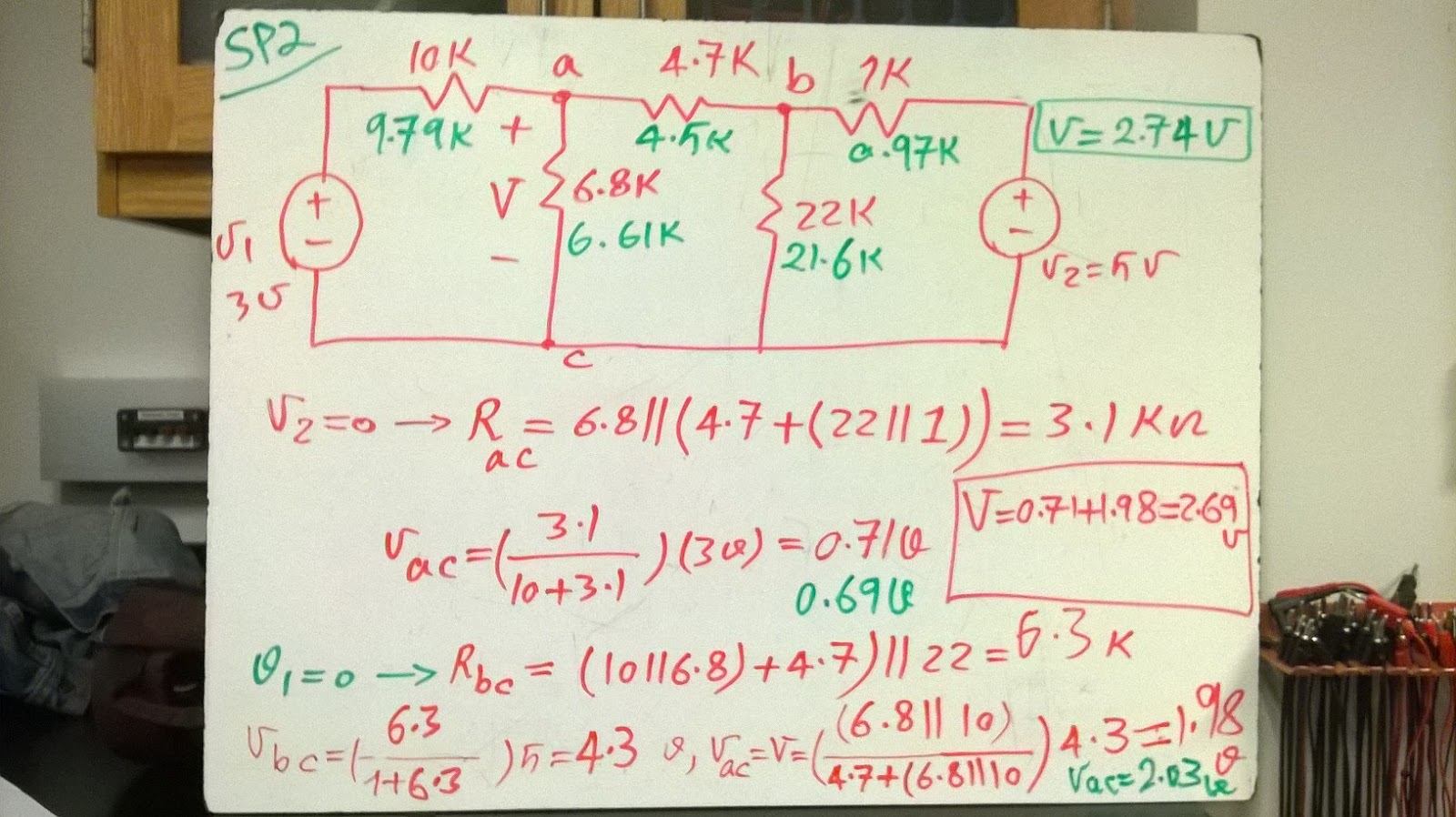
Figure 1: Calculations for a Thermistor

The resistance versus temperature curve

of a thermistor is not linear curve, but it is

linear between 25 - 37 centigrade degrees.

In the circuit a NTC (Negative Temperature

Coefficient) is used. This means, when

temperature goes up, the thermistor resistance

goes down. Input voltage of the circuit is 5 v and output voltage varies by a minimum of 0.5 v over a

temperature range of 25 C to 37 C. So, output voltage must increase as temperature increase.

According to Fig 1, when the temperature goes up, R(th) goes down, and its drop voltage goes down.

Therefore, V(out) increase because V(in) = V(th) + V(out). According to the curve of thermistor,

R(25) = 10600 ohms and R(37) = 7400 ohms. V(out) = [R / (R + R(th) )] * V(in).

This formula is used Vout (37 C) - Vout (25 C) = 0.4 volts  and R = 4 k , R = 18 k is calculated.

Vout (37 C) = [ 4 / (4 + 7.4)]*5 = 1.8 volts , Vout (25 C) = [ 4 / (4 + 10.6)]*5 = 1.4 volts

1.8 - 1.4 = 0.4 volts.

Vout (37 C) = [ 18 / (18 + 7.4)]*5 = 3.5 volts , Vout (25 C) = [ 18 / (18 + 10.6)]*5 = 3.1 volts

3.5 - 3.1 = 0.4 volts.
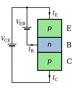
Figure 2: Thermistor resistance of the body Temperature

According to the thermistor curve,

Rth (33 C) = 8.4 k  & Rth (25 C) = 10.6 k

Rth (33 C measured) = 7.3 k

Vout (33 C measured) = 1.88 v

Rth (25 C measured) = 10.95 k

Vout (25 C measured) = 1.32 v

percent voltage error (25 C) = [(1.4 - 1.32) / 1.32]*100 = 6.1%

percent voltage error (33 C) = [(1.88 - 1.8) / 1.8]*100 = 4.44%

Figure 3: A Schematic Circuit
Figure 4: Operation of Thermistor Circuit Movie
The output sensitivity of the device must be at least 0.1 V/C.

According to temperature - resistance curve in Laboratory Manual:

1) A linear equation is calculated.

Rth = -(266.67)*T + 17266.8 

Line Equation
According to above equation, when T ≥ 52.2496 °C → Δ ≥ 0

Therefore, quadratic equation for R has real root. But 52 °C is not in temperature interval of line equation.
So we can change dVout / dT = 0.1 Volts / °C.

So dVout / dT = 0.0314 is suitable , and R = 11450 ohms or R = 9812 ohms